
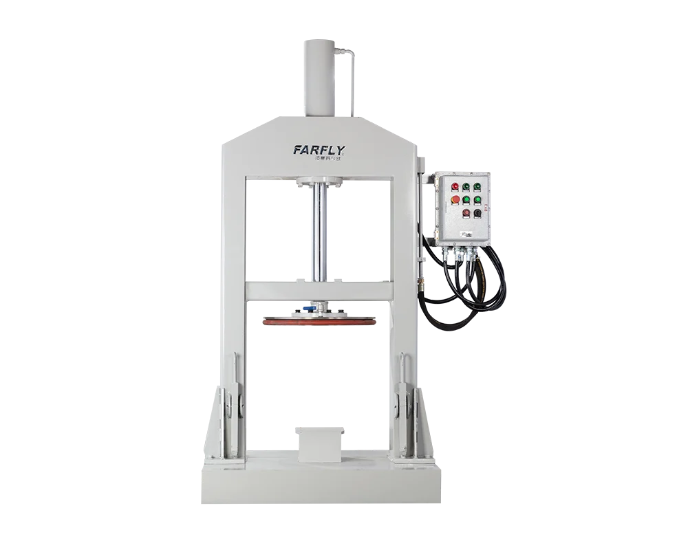
FYL Hydraulic Discharging Machine

A hydraulic ram press designed to remove high-viscosity adhesives, sealants, inks and resins from movable mixer vessels. The sealed pressure plate applies controlled force to deliver material through a bottom outlet or plate-mounted pipeline to filling, packaging or the next production stage.
For materials up to 5,000,000 cps
Tank diameters from 900 to 1200 mm
Single-cylinder or three-cylinder designs
Supports discharge, filling & transfer
Operating Principle
Hydraulic Ram Press
Pressure plate forces material from the vessel
Viscosity Range
Up to 5,000,000 cps
Subject to material and discharge conditions
Tank Diameter
900–1200 mm
Four published standard models
System Integration
Mixer to Filling
Discharge, manual filling or transfer
Discharge Principle

How Does the FYL Hydraulic Discharging Machine Work?

Highly viscous material may not flow from a mixer vessel under gravity. Manual removal is slow, labor-intensive and can leave a large amount of usable product on the vessel wall.

The FYL positions a hydraulic pressure plate above the material vessel. As the plate descends, a vessel-matched sealing ring contacts the wall and forms a closed working space. Hydraulic force then pushes the material toward the selected outlet for controlled transfer to filling or downstream equipment.

The pressure plate supplies the force that high-viscosity material cannot generate by gravity, while the wall seal helps direct more product toward the outlet and reduce retained residue.
Pressure and Sealing Working Together The ram plate creates controlled downward force while the sealing ring follows the vessel wall.
01

Hydraulic Pressure Plate

Applies stable downward pressure to move non-flowing or slow-flowing material out of the vessel.

02

Vessel-Matched Sealing Ring

Maintains close contact with the vessel wall to form a sealed space and guide material toward the outlet.

Machine Design

Key Design Features of the FYL Discharge Press

The FYL is built around a rigid frame, hydraulic lifting and pressing system, vessel-matched pressure plate and configurable material outlet.
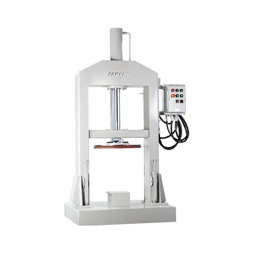
FYL hydraulic ram press structure with pressure plate
01
Hydraulic Drive SystemProvides controlled lifting and pressing force for stable discharge of very viscous material.
02
Ram Pressure PlateTransfers hydraulic force across the material surface to push product toward the discharge point.
03
Precision-Matched SealThe sealing ring is matched to the vessel diameter to maintain wall contact during the pressing stroke.
04
Flexible Outlet ArrangementMaterial can be discharged through a vessel bottom outlet or a pressure-plate pipeline configuration.
05
Single- or Three-Cylinder StructureHydraulic structure can be selected according to vessel size, force and production requirements.
06
Fixed or Lifted Vessel DesignRaised-vessel or fixed-vessel arrangements can be evaluated for different plant layouts.
Applications & Process Fit

High-Viscosity Material Discharge Applications

The FYL is intended for materials that do not discharge efficiently by gravity and need positive hydraulic force for transfer, filling or packaging.

01 / ADHESIVES

High-Viscosity Adhesives

Transfers dense adhesive batches from movable mixer vessels to downstream filling or packaging.

02 / SEALANTS

Silicone & Structural Sealants

Applies positive pressure to materials that resist gravity discharge after planetary mixing.

03 / INKS

High-Viscosity Inks

Supports controlled removal and transfer of paste-like ink formulations from matched vessels.

04 / RESINS

Resins & Polymer Compounds

Suitable for dense resin systems requiring sealed, pressure-assisted discharge.

05 / PASTES

Filled Industrial Pastes

Helps move highly filled products whose solids loading limits natural flow.

06 / PRODUCTION LINE

Mixer-to-Filling Transfer

Connects planetary mixing with manual filling, metered filling or the next processing stage.

Especially Suitable When Your Process InvolvesActual discharge performance depends on rheology, temperature, outlet and downstream back pressure.
01Material that will not flow under gravity
02Viscosity up to the published 5,000,000 cps limit
03Movable vessels from planetary mixers
04Reduced manual handling and scooping
05Controlled transfer to filling equipment
06Lower retained material on vessel walls
Equipment Selection Logic

When Should You Choose an FYL Hydraulic Discharger?

The FYL is most useful when discharge—not mixing—is the production bottleneck and a viscous batch cannot be transferred efficiently from the mixer vessel.

01

Gravity Discharge Is Too Slow

The ram plate supplies positive pressure to move material that otherwise remains in the vessel.

02

Manual Removal Creates Labor and Waste

The vessel-matched sealing plate helps direct more product to the outlet and reduces manual scraping.

03

The Mixer Must Connect to Filling

The discharge system can feed manual filling, packaging equipment or another downstream process.

Discharging a pumpable liquid? If the product already flows easily, a transfer pump may be a simpler solution. The FYL should be selected when positive ram pressure is justified by material rheology and vessel arrangement.
Technical Data

FYL Hydraulic Discharging Machine Specifications

Standard published models cover vessel diameters from 900 to 1200 mm. Final plate and sealing dimensions must match the actual material vessel.

ModelMotor PowerTank DiameterPressure Plate DiameterMaximum Lift
FYL-9004 kW900 mm900 mm1150 mm
FYL-10004 kW1000 mm1000 mm1150 mm
FYL-11005.5 kW1100 mm1100 mm1250 mm
FYL-12005.5 kW1200 mm1100 mm1250 mm

* Standard reference data from FARFLY. Note that the published FYL-1200 pressure plate diameter is 1100 mm while its tank diameter is 1200 mm; confirm the intended vessel and sealing arrangement before quotation. Final configuration depends on vessel dimensions, material behavior, required flow and outlet design.

Configuration Options

Available FYL Discharge System Configurations

Cylinder structure, vessel arrangement, sealing plate and outlet route can be configured around the mixer vessel and downstream filling process.

ComponentAvailable ConfigurationSelection Basis
Hydraulic StructureSingle Cylinder / Three CylinderMatched to pressing force, vessel size and structural requirements.
Vessel ArrangementRaised Vessel / Fixed VesselSelected according to plant layout, outlet elevation and downstream connection.
Pressure PlateVessel-Matched DiameterRequires confirmation of internal vessel dimensions and manufacturing tolerance.
Sealing RingMatched Seal DesignSelected according to vessel wall, material compatibility and service conditions.
Discharge RouteBottom Outlet / Plate PipelineMatched to filling equipment, transfer distance and required product path.
Downstream ProcessManual Filling / Transfer / PackagingSelected according to target flow, dosing method and production rhythm.
Standard Tank Diameter900 / 1000 / 1100 / 1200 mmFinal selection must match the actual movable or fixed material vessel.
Typical Process

Typical High-Viscosity Discharge Workflow

A typical mixer-to-filling workflow may use the following steps.

01
Move or Position VesselThe completed mixer vessel is placed and aligned beneath the discharge press.
02
Align Pressure PlateThe plate and sealing ring are centered with the vessel before descent.
03
Seal & PressThe hydraulic system lowers the plate and applies controlled pressure to the material.
04
Transfer or FillMaterial exits through the configured route to filling, packaging or downstream processing.
05
Retract & Change OverThe pressure plate lifts so the vessel can be removed for cleaning or the next batch.

Actual pressing pressure, speed and discharge rate depend on viscosity, thixotropy, temperature, outlet size, transfer distance and downstream back pressure.

Equipment Selection

What We Need to Configure Your FYL

Tank diameter alone is not enough. Provide the following information so pressing force, plate, seal and outlet design can be evaluated together.

Material & ViscosityProvide product type, processing temperature and viscosity or flow behavior.
Vessel DimensionsShare internal diameter, straight-wall depth, outlet position and manufacturing tolerance.
Batch WeightSpecify material weight and density to estimate the total discharge duty.
Required Flow RateState target discharge rate or filling-cycle requirement.
Outlet & PipelineProvide outlet diameter, transfer distance, height and downstream back pressure.
Downstream EquipmentConfirm whether material feeds manual filling, a filling machine or another process.
Material CompatibilityIdentify temperature, solvent and chemical conditions relevant to seal selection.
Engineering Support

Match the FYL to Your Mixer and Filling Process

FARFLY can evaluate the discharger as part of the complete high-viscosity production line rather than as an isolated press.

01

Material Review

Viscosity, thixotropy, density and temperature establish the discharge requirement.

02

Vessel Matching

Plate and sealing geometry are matched to actual vessel dimensions.

03

Hydraulic Selection

Cylinder arrangement and pressing duty are evaluated against material resistance.

04

Outlet Design

Bottom or plate-pipeline discharge is selected around the downstream connection.

05

Line Integration

Mixer vessel handling, filling, transfer and cleaning are aligned with the plant workflow.

FAQ

FYL Hydraulic Discharging Machine FAQ

Common questions when selecting a hydraulic ram press for adhesives, sealants, inks and resins.
What is an FYL hydraulic discharging machine?
The FYL is a hydraulic ram press that uses a sealed pressure plate to force high-viscosity material from a mixer vessel through a bottom outlet or pressure-plate pipeline.
What viscosity can the FYL discharge?
FARFLY publishes the FYL for high-viscosity adhesives below 5,000,000 cps. Actual performance depends on temperature, thixotropy, outlet size, pipeline and downstream back pressure.
Which mixers can the FYL work with?
It is designed as supporting equipment for double planetary power mixers, planetary mixers and multifunctional mixers using compatible material vessels.
Does the FYL eliminate all vessel residue?
The vessel-matched sealing plate is designed to reduce retained material on the vessel wall and direct more product to the outlet. Actual residue depends on vessel tolerance, seal fit and material behavior.
What cylinder configurations are available?
FARFLY lists single-cylinder and three-cylinder structures. The suitable arrangement depends on vessel size, pressing force and the production layout.
What standard vessel diameters are listed?
The published standard range covers tank diameters of 900 mm, 1000 mm, 1100 mm and 1200 mm.
Where can the discharged material go?
The material can be directed to manual filling, packaging equipment, transfer piping or another downstream processing stage.
What information is needed for selection?
Provide material type, viscosity, temperature, density, batch weight, vessel dimensions, outlet size, required flow, transfer distance and downstream equipment.
Scroll to Top

Get A Free Quote Now !

Contact Form Demo
If you have any questions, please do not hesitate to contact us.